
AtlaX Concept [Part 2]
Go to Part 1 – Imagining something new
Part 2 – Build a concept
Technical choices
No linear actuator: due to the turntable and the geometry of the main arm it will bring a lot of difficulty to install and no better result than pneumatic.
No PF nor RC: after few tests I came to the conclusion that one or two mini pump actuated by a PF-M or L motor wouldn’t be powerful enough to raise the bucket. A manual pump from set 42053 will be used.


The chassis
The chassis is a rigid frame supporting all the component of the vehicle.
At the forward extremity can be found the turntable and the engine compartment is installed at the rear end.
It is mounted on 4 tracks, each 4 tracks are interchangeable and installed on small turn table. They are pendular and can accommodate any type of topography.


Inside the engine compartment is installed all the pneumatic system: one large pump and two new switches. There is also an angle gear that allows controlling the rotation of the turntable. Unfortunately it wasn’t possible to install a fake engine, but since the compartment can’t be open it is not real lack.

All the function on the AtlaX can be controlled with both hands on the engine compartment.
The switches are installed on each side and controlled through 20t gear. The switch controlling the main arm elevation has only the “raising” pneumatic exhaust installed. To lower the arm the pressure is simply released and it goes down under its own weight.
On the rear end of the machine is also installed a drum for “electrical connection to an external generator”. This is inspired by the giant mining excavator working on full electric with no thermal engine on board.


The superstructure
It supports both arms and cabin.
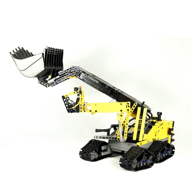
The main arm is articulated on two mini turntable. This allows a compact dimension when folded but a high height reachable when deployed. It is actuated by two long pneumatic cylinder. The bucket (from set 42030) is tilted by two long-thin pneumatic cylinder.


The cabin is installed on a foldable structure allowing a large range of movement. It can be lowered to the ground and raised high for a perfect view of the working area. The folding structure is composed of two parallelogram which always maintain the cabin parallel to the ground. In addition, two axle joiner maintain the assembly in the correct position.


Some platform with handrail are installed around the main arm. For maintenance purpose.

Final words
All the stickers used on the MOC come from official Lego-Volvo set 42030 and 42053.
This is a personal creation, not an official Lego set. You can’t buy it in a store.
It is not planned to put online digital file and put it for sale on MocHub. I may reconsider the question after the contest ends.